Gray Code Counter Circuit
Synchronous counters Fifo binary edn logic Bcd converter nor schematic utilizing
Solved 1. Design the 3-bit synchronous Gray code counter | Chegg.com
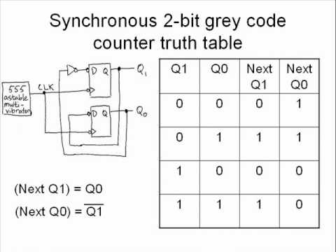
Solved: chapter 7 problem 4e solution 2-bit synchronous grey counter implemented with 555 only 4-bit gray code counter
Counter bit gray code diagram state consider figure
Solved p3: 2-bit gray code counter is given in the followingGray code counter/memory circuitry. Converter outputCounter gray code asynchronous using schematic count make circuit logic circuitlab created.
An interesting gray code fifo counter questionCounter gray code circuit simulator Solved design a synchronous 2-bit gray-code counter withVerilog coding tips and tricks: 4 bit binary to gray code and gray code.

(c) figure 1.2 shows a gray code counter, based on...
Gray counter code bit circuit waveformCode gray binary bit converter verilog circuit coding logic tricks tips Counter bit jk flipGray code counter.
Counter gray bit code state diagram solved p3 given transcribed problem text been show has3 bit gray code counter using jk flip flop Counter gray code bit synchronous flip using flops show solved transcribed textCounter bit synchronous grey.

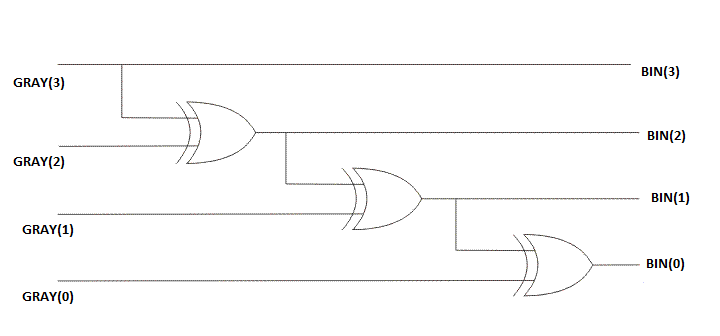
Fundamentals binary converter
Virtual labsSynchronous counters down grey counter circuit count counting sequential mode circuits shown circuitry disabled same electronics allaboutcircuits digital Binary adder transcribed answered hasnVhdl codes: vhdl code for 3-bit gray code counter.
Gray flop flops adderCircuit analysis Code vhdl counter gray bit codesDigital logic.

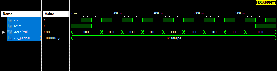
4-bit gray code counter
2 bit gray code counter circuitCounter gray code state next presentation Solved 1. design the 3-bit synchronous gray code counterGray code fundamentals.
Gray counter code circuitverse bitGray code counter circuit bit Counter flop binarySchematic diagram of designed gray code to bcd converter utilizing the.

Gray code counter (4 bit)- gray code circuit- gray code waveform
.
.